This is a gripper mounting bracket for a robotic application I made a few years ago. I have since made three others with the same basic configuration. It was made from two 1/4 inch steel plates welded to a 2 inch x 1/16 inch thick square tube. The round end bolts to the robot arm. The square end has a symmetrical bolt pattern with bolt holes and pin locating holes for mounting the gripper mechanism. The bracket was TIG welded using my Miller Dialarc welder (it’s old and huge but works great – And has a water cooled torch!).
Preparation
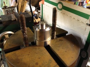
The bracket mounting plates were made from plain square flat stock. After drilling the bolt and pin hole pattern in the robot mounting bracket, it was turned round in a lathe so that its outer diameter would be a close match to the diameter of the robot arm mounting flange.
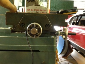
The square tube was cut slightly over length and the ends were squared in a mill so that both end bracket surfaces would be very close to parallel after welding.
Robot Mounting Flange
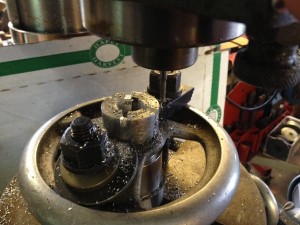
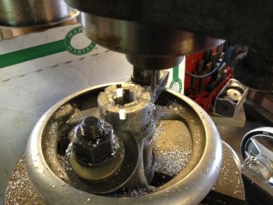
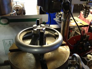
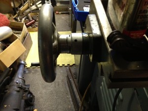
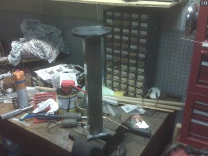 The round flange is on the end attached to the robot arm. It was made it first so that I would have a jig locating surface and mounting holes to attach to so that the gripper mounting flange end could be accurately machined. Notice the hole in the center of the round plate. It’s there so that the bracket can be mounted in a lathe. Why? The flanges warp when they are welded to the tube and the mounting surface must be squared so that it will lay flat against the robot mounting surface. For me, it was much easier to mount the bracket in the lathe and turn the surface true than to mount it in the mill and machine it flat.
Welding The Bracket
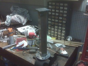 Alignment marks for positioning the square tube were scribed on the robot mounting flange. Note that the position of the square tube and even the position of the gripper mounting bracket did not have to be perfectly aligned. Why? The gripper mounting surface and mounting holes were yet to be machined. The hole positions are relative to the locating pins in the machining jig as seen later in this post. It doesn’t matter so much where the gripper flange is as long as it’s not too far off position.
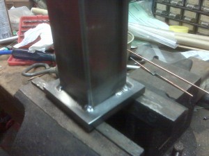 The tube was placed in between the bracket flanges and clamped with a long ratcheting squeeze clamp. The corners of the tube were tacked first, starting on one side and moving to the opposite side for the next weld. When welding a bracket such as this I try to stagger the welds in small even amounts so that the warping and stress in the part is spread out as evenly as possible. After all four corners of the tube were tacked I finished by welding slightly farther past the corners of the tube. The same basic procedure was used for both bracket flange ends.
Machining The Gripper Flange
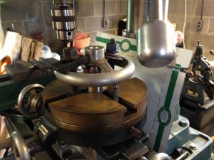
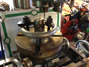
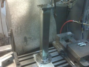 A jig plate was made from 1/2 inch aluminum bar stock. Clamping bolt holes were drilled and tapped and pin locating holes were drilled to align the robot flange end of the bracket. The jig plate was then bolted to the mill bed and aligned square to the x and y axes of the mill.
The mill has a DRO (digital read out – for those unfamiliar) which was used to locate and set a known zero point at the center of the jig mounting holes, which was also the center of the bolt pattern of the robot flange plate. The bracket was then mounted on the jig and a light skim cut was milled on the gripper flange to eliminate the previously mentioned warping. Next, the mounting holes and locating pin holes were machined in the gripper flange.

